
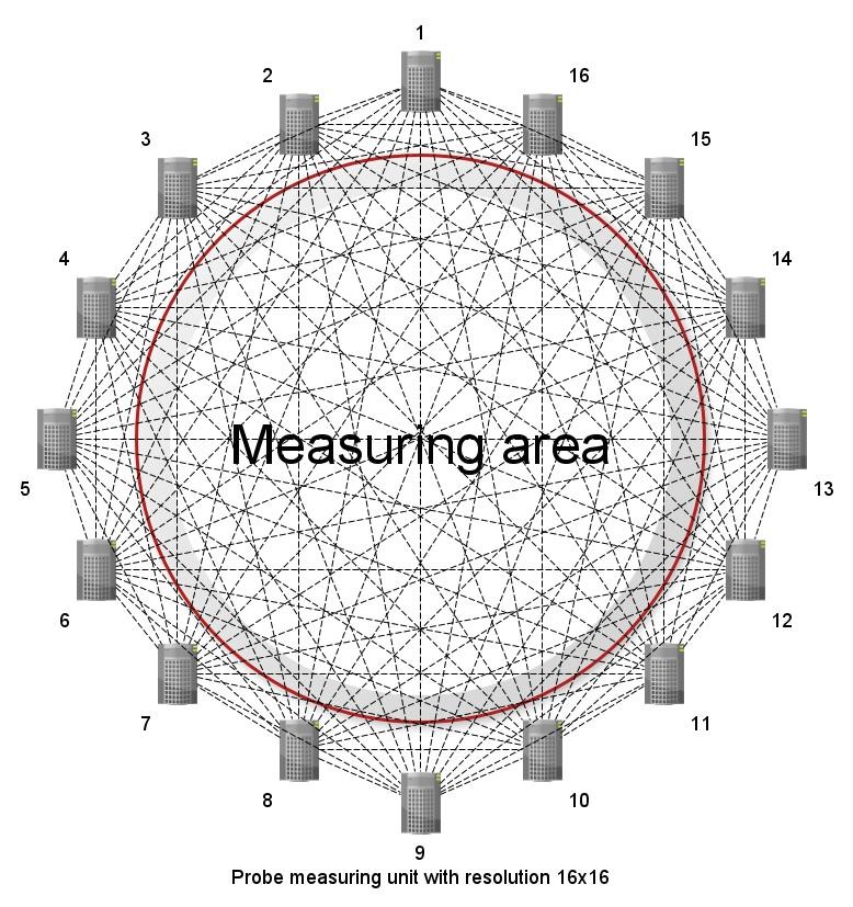
Fig. 1. All projection angles and the resulting grid in a 16 × 16 RF tomograph system
Michał Styła
1Research & Development Centre Netrix S.A
University of Economics and Innovation, Lublin, Poland
Keywords: Simultaneous localization and mapping, Indoor navigation, Tomography, Image reconstruction, Radio frequency integrated circuits, Bluetooth
Introduction
Tomography is a word that combines two other words from Greek, i.e. cross-section (tomé) and write (grafein). As a process, it always aims to obtain a cross-section of an object using a relatively non-invasive medium. In practice, this means the integrity of the material integrity of the tested object.
The created tomographic system uses electromagnetic waves of 2.4 GHz frequency and power not exceeding 6.3 mW (+8 dBm) as a transmission medium. The selected frequency range works very well in the detection of organic objects due to the high degree of absorption by water. The power is sufficient for the system to cover small and medium-sized rooms with its operation. The system can be successfully scaled with higher power modules or antennas with higher energy gains.
- Measurement algorithm of the radiotomograph
The model presenting the operation algorithm of the radio tomograph is presented in Figure 1. The created system may consist of any number of radio measurement probes (sixteen in the tested case), which, using the RSSI (Received Signal Strength Indication) indicator, are able to perform a two-dimensional space mapping.
The probes, alternately connecting with each other and exchanging data, create individual projection angles, which at the end of the process form a measurement grid. Its density is strictly dependent on the number of radio probes used and the manner of their arrangement in relation to each other and the shape of the room. In order to avoid collisions of data streams at individual projection angles, the software of radio probes was deprived of decision-making abilities in relation to the measurements performed. The burden of control and the responsibility to maintain data integrity has thus been transferred to the central control unit.
- Hardware layer
The smallest cell building the created system is the tomographic radio probe shown in Figure 2. There are three basic sections on the probe PCB surface.
The upper left corner is occupied by a power section equipped with a galvanic cell charging controller, signaling of energy processes by means of light-emitting diodes, and a standardized USB micro port. The process of charging the cell can be recognized by the steady light of the orange light in the lower left corner of the device (picture 4). The whole thing has been protected against short circuit with a fuse.
On the opposite side of the PCB there is a control and computing section, the most important element of which is the STM32 microcontroller from the energy-efficient L0 series, built with ARM Cortex M0 + cores. All communication ports of the device converge here. The reprogramming of the microcontroller can be done at any time using the STLink / V2 programmer connector. It also provides an alternative power path for the probe. When the connection with the device is lost, the reset can be forced using the button in the top right corner of the PCB. In order to increase the adaptability of the system in the lower right corner, three control buttons have been added for general applications depending on the software version in the microcontroller’s memory.
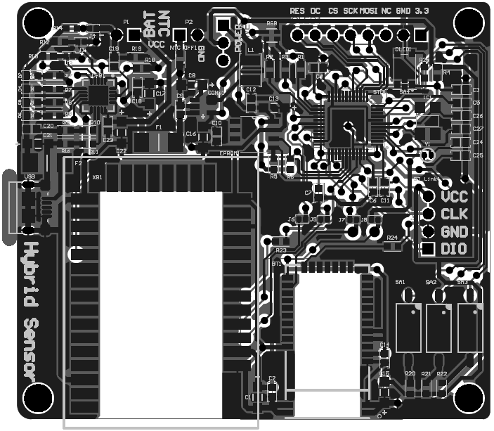
Fig. 2. PCB mosaic of a radiotomographic probe designed for a room navigation system
The last area is surfaces completely devoid of copper layers (white areas in Figure 2). They are occupied by Bluetooth and XBee communication modules. They have been configured in such a way as to best provide services for radio tomography. Each module has its own transmitting and receiving antenna, which allows both communication standards to work independently at the same time. Additionally, to increase the number of parallel operations (which has a direct impact on the overall speed of the system), all UART interfaces between the modules were configured in full-duplex mode.
Signaling of the operation mode and status of the radio tomograph was carried out by means of an RGB light-emitting diode. The green color indicates the use of the XBee wireless module by the tomograph, and the blue color has been reserved for signaling the activity of the Bluetooth module. During the measurement, the red color lights up briefly, which makes it easier for the user to observe and analyze the system during operation.
- Integration of system components
The system was integrated with a central control unit built from a Raspberry Pi Zero W single-chip computer with Bluetooth and Wi-Fi communication. Enriching the system with support for communication with XBee modules required the design of a separate adapter. The whole thing (together with the mounting of the omnidirectional antenna led out to the outside) was closed in a special housing equipped with heat dissipation.
The central control unit ensures the correct sequence of measurements, acquisition of measurement data, pre-processing and sending of these data to a selected platform via Wi-Fi and MQTT protocol, as well as faster detection of measurement errors. Thanks to the use of such a hierarchy between devices, reconstruction can be performed on any selected unit of computing, provided that it is able to correctly interpret the data converted to the JSON standard.
- Reconstruction of the room
The room reconstruction process is strictly sequential. In a first step, the central control unit forces each individual radio probe to exchange RSSI data with all other sensors surrounding the test area. In this way, the CPU obtains one row of the measurement matrix from each individual probe (Figure 3). The data is processed with a parser written in Python 2.7 and prepared for transmission to the MQTT server
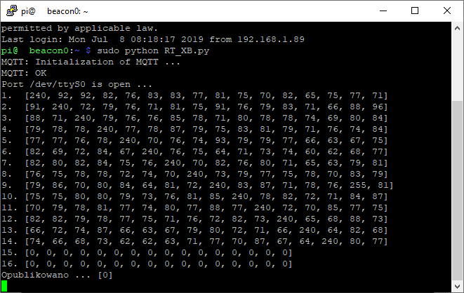
Fig. 3. Software implemented in the central control unit during the acquisition of measurement data
In order for the system to be able to detect objects that violate the space of the room, the tomograph must first perform the so-called background. The background is a reconstruction of the room that serves as a comparative element for each next one. This process can be compared to the calibration of a measuring instrument. Background measurement is an image of the room intact by any living organisms and non-permanent elements of the environment, so it does not have to be performed every time the system is started. In the presented configuration it is stored as a ready pattern on the end (reconstructing) device. A comparative analysis in combination with the use of computational elements such as Tikhonov’s regularization or the Mexican Hat filter allowed to obtain the view presented in Figure 5.
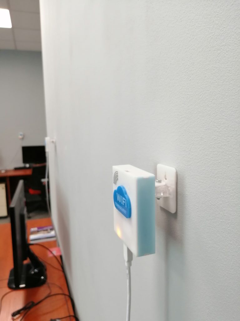
Fig. 4. View of the method of making a fragment of the radiotomograph in the tested room.
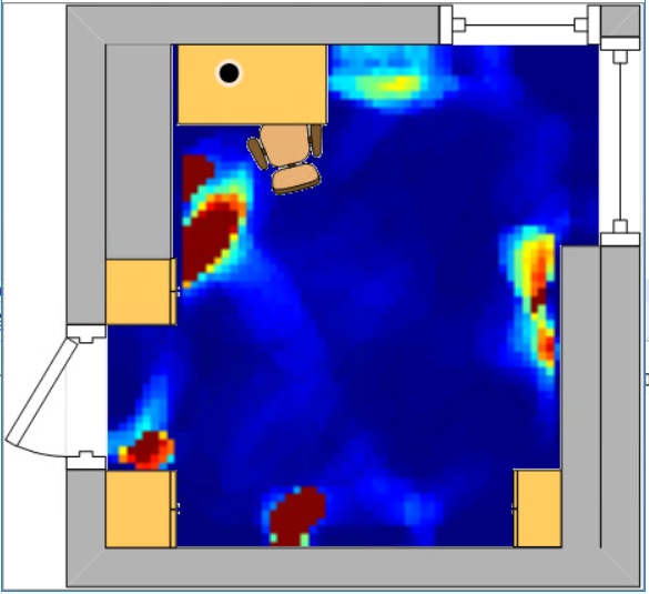
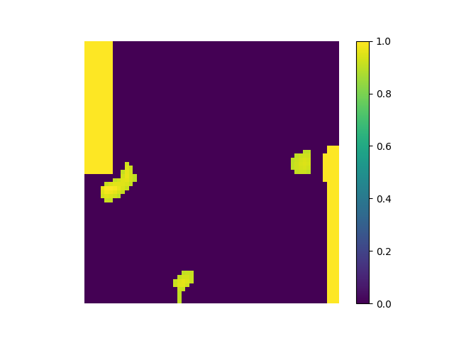
Fig. 5. Room reconstruction (top) and heat map (bottom) obtained with a radio tomograph
- Summary
The use of all the previously described elements for the construction of the radio tomograph resulted in the creation of a fully scalable and flexible system supporting the imaging of rooms using electromagnetic waves. By means of common denominators in the form of standards such as Bluetooth, XBee or Wi-Fi, the tomograph can be easily made part of larger navigation networks, thus increasing their accuracy.
Bibliography
- Maj M., Rymarczyk T., Kania K., Niderla K., Styła M., Adamkiewicz P.: Application of the Fresnel zone and Free-space Path for image reconstruction in radio tomography, International Interdisciplinary PhD Workshop 2019, IIPhDW 2019, 15 – 17 May 2019, Wismar, Germany.
- Rymarczyk T., Styła M., Oleszek M., Maj M., Kania K., Adamkiewicz P.: Object detection using radio imaging tomography and tomographic sensors, Przegląd Elektrotechniczny, ISSN 0033-2097, R. 96 NR 1/2020